Project 04 · Case study
Inclining Transparent Walkway (Vibram Senior Design)
Vibram wanted to film shoe soles from under a walking person; we delivered a transparent walkway inclining 0–40° with a 500 lb design load.
Getting to delivery meant killing our leading mechanism two-thirds through and verifying its replacement — the work of four rounds of FEA across six months.
What Vibram asked the walkway to do
The load requirement carried a safety factor of two on the person’s weight, increasing the maximum weight for the walkway from 250 to 500 pounds. The lift had to be mechanical — the $2,500 budget pretty much ruled out electrical solutions anyway, and the customer did not want electricity. The finished unit also had to fit through a door into the facility, and that requirement is what set the walkway’s width.| Requirement | Target | Achieved | Verified by |
|---|---|---|---|
| Incline in fixed steps (relaxed from 0–45° in 5° steps) | 0–40°, 10° steps | met — bench pins natively index 0–40° in 10° increments, one bolt pair per angle | delivered device, demonstration |
| Support a walking person with SF 2 | 500 lb | by analysis — FEA passed at 500 lb; the walk-on peaked at about 450 lb | SolidWorks FEA + hand calcs + walk-on test |
| Fully mechanical lift, no electricity | — | met — bench pins + gas struts + hand-cranked camera carriage | inspection of delivered design |
| Transparent 66 × 24 in walkway | 66 × 24 in | met — 0.75 in cast acrylic, 24 × 66 in | BOM + delivered device |
| Operable by one person (two acceptable) | 1 person | met — one pull releases both bench pins; gas struts nearly self-lift the ramp | use during validation; no formal test documented |
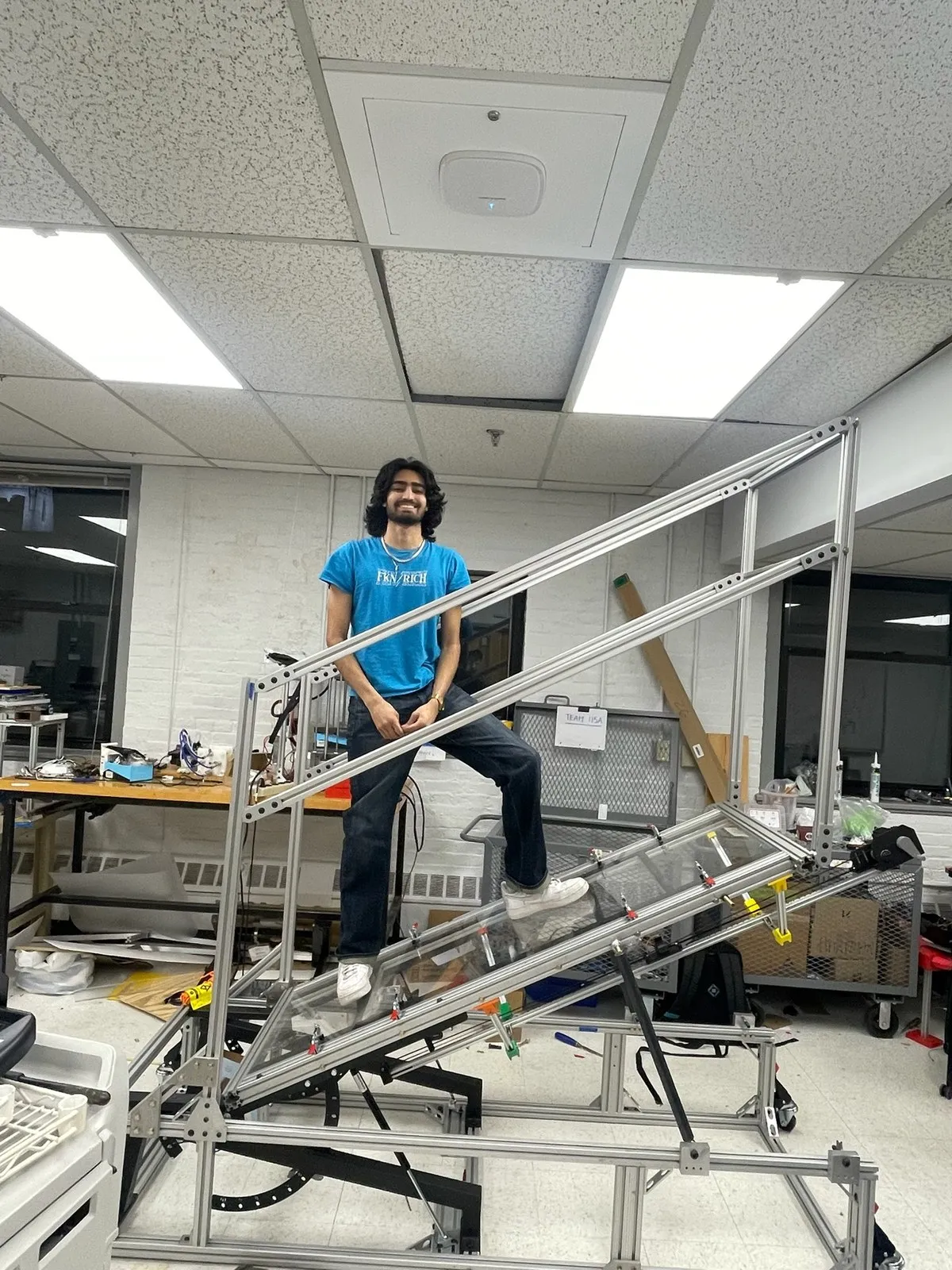
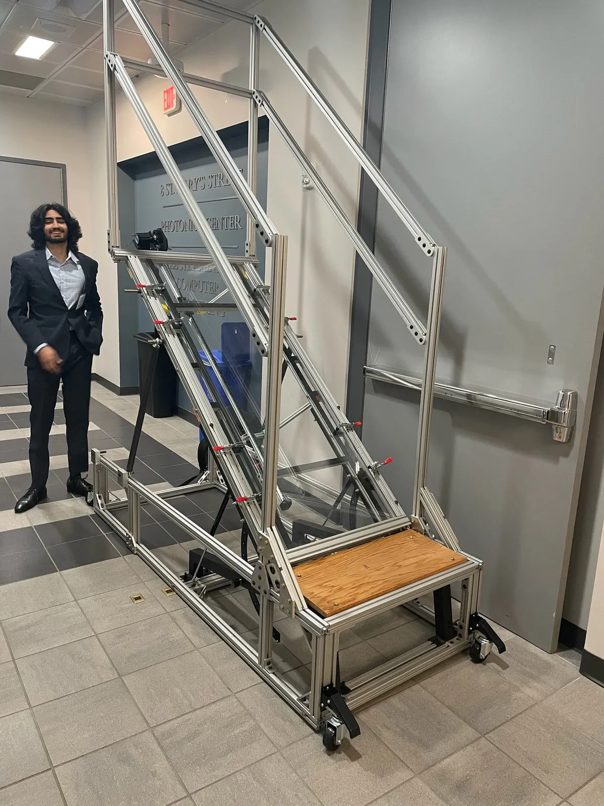
| Railings on top of the walkway | — | met — parallelogram handlebars, back bar vertical at any angle | delivered design |
| Removable acrylic, modular, stock parts | — | met — toggle clamps release the panel; all-bolted 8020; nearly every part off the shelf | delivered design |
| Easy to move on wheels | — | met — retractable casters | delivered design; no mobility test documented |
| Camera perpendicular to the walkway at all times | 90° | partial — rail rides parallel to the acrylic frame at every angle; image capture validated at 0° only | presentation evaluation slide |
| Maximum cost | $2,500 | not met — 2025-03-10 BOM totals $2,926.21 with buffer | bill of materials |
| Fit through a door into the facility | — | met — delivered into the Boston Connection Lab | delivery |
Concepts for the lift mechanism
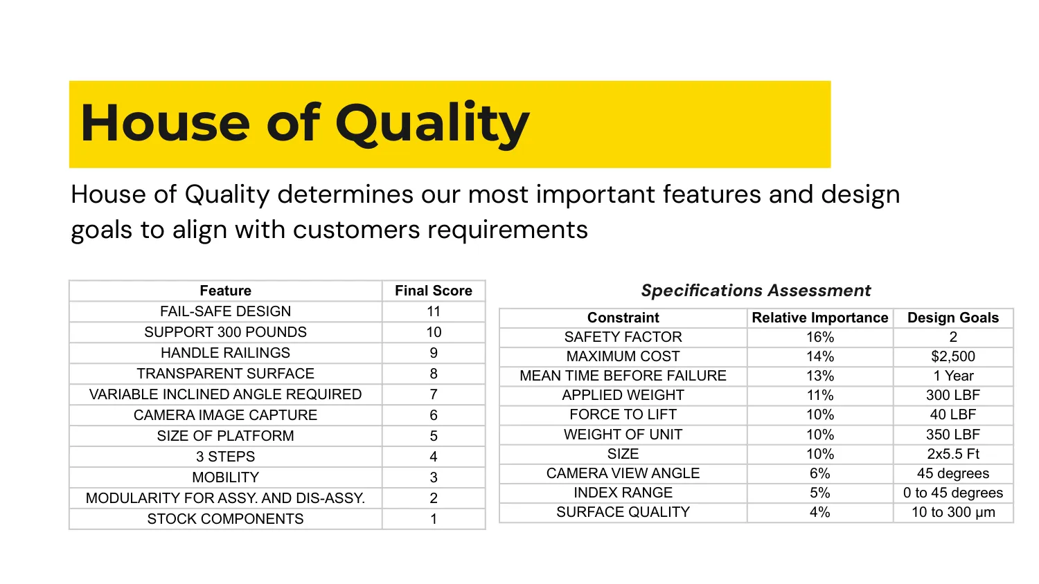
The lifting and indexing concepts on the table: hydraulic, jack, scissor jack, two pulley variants, winch, crank, linear slide, lead screws, a simple human lift, and a beach-chair locking mechanism. The scissor jack was mine.I organized the House of Quality that scored all of it: fail-safe design ranked most important, and the specification weights put safety factor first at 16% (design goal 2) with maximum cost second at 14% ($2,500). The Pugh analysis reused those HoQ weights, and the manual human lift scored highest on simplicity and low cost. The candidates also got deflection numbers: we modeled the jack design as a cantilever with a composite acrylic-and-aluminum modulus of about 2.19 × 10⁶ psi, where a 400 lb load at the end of the walkway deflected it 0.743 inches with the jack 2 feet along — moving the jack to 3 feet cut that to 0.27 inches. The full matrix and weighting method are in the House of Quality report.
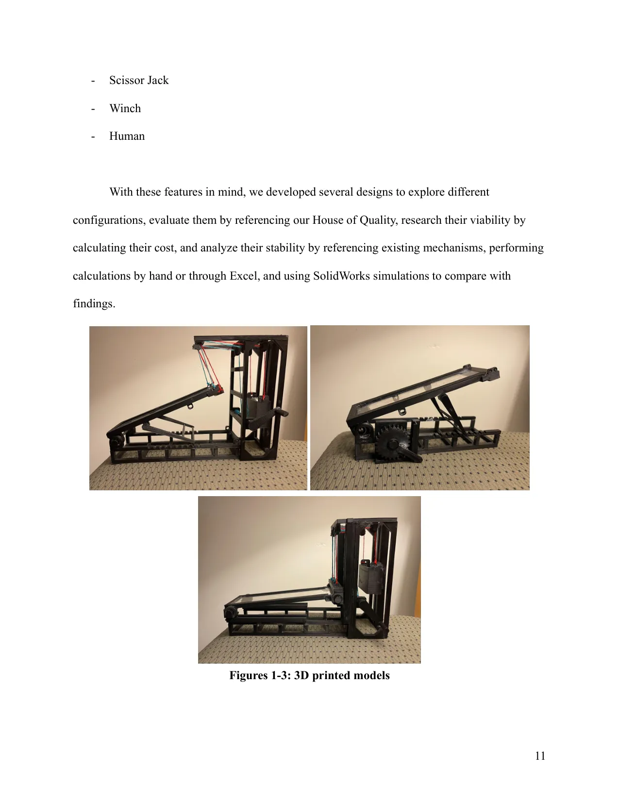
That’s the design we carried out of the fall: a manual lift with lawn-chair indexing — machined grooves in steel tubing as index points, a steel bar slotting in, clevis-ended aluminum struts up to the acrylic cage. The fall down-select and design are documented in the fall halfway report.
Why we dropped the beach-chair mechanism
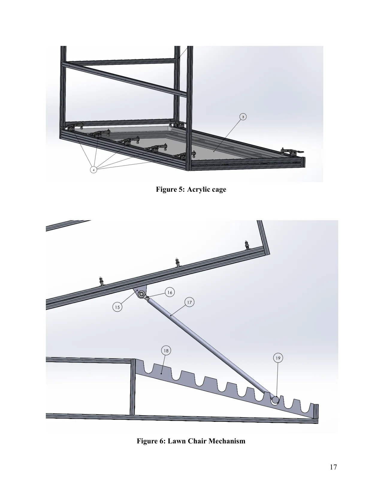
The strikes had been accumulating anyway: the hinge point was costly to manufacture, operating it was strenuous, the lift-lower-move-the-strut sequence was too complicated, the machined index teeth came out costly and imprecise, and we could not verify a high enough factor of safety. About two-thirds of the way through, we killed it completely and pivoted. The pivot cost less than it sounds: the frame was highly integrable, so only the bench-to-base and bench-to-frame interfaces changed — not a lot of trouble at all to move pieces of 8020 around.There was simply no way to support the weight we wanted with that mechanism.
Two 1,200 lb gym benches as the lift
What replaced it was prefabricated: two home gym benches, modified and bolted into the base frame. Each bench is rated 1,200 lb by its manufacturer, its alloy-steel pin mechanism natively indexes to 40 degrees in 10-degree increments, it’s a stock product Vibram can repurchase, and it hits the top two House of Quality criteria — fail-safe design and 300+ lb. The lift that replaced months of our own mechanism design cost $69.99 a bench. We trusted the 1,200 lb rating as a starting point, then verified it — FEA before assembly, physical testing after.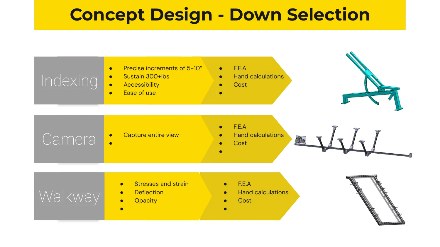
Integrating them was one of my subsystems, and it reused the benches’ own hardware: the pads people lean on came off, and their existing screw holes were designed to line up with the 8020 — each bench’s inclinable portion bolts to the acrylic frame, its base into the base frame. The subsystem down-selection is in the spring 2025 presentation.
A beam ties both bench pins together through 3D-printed connectors, so pulling one handle pulls both pins at once. The two gas struts — IAQWE 28-inch, 120 lb heavy-duty — are sized to almost entirely lift the ramp by themselves from the compressed state; with the pins out, the user adds only a few pounds of force, and the pins hold everything the rest of the time. The load path at incline was the late fix: the original plan had the benches cantilevering the walkway’s weight, I calculated that was not feasible, and removable steel tube supports were added late. Each tube bolts to the sides of both ramp frame and base, and I calculated the bolt positions so each pair yields exactly 10, 20, 30, or 40 degrees — on the BOM they’re 4 ft and 6 ft carbon steel rods with ball-joint rod ends, the short and long struts the user installs for the height they want.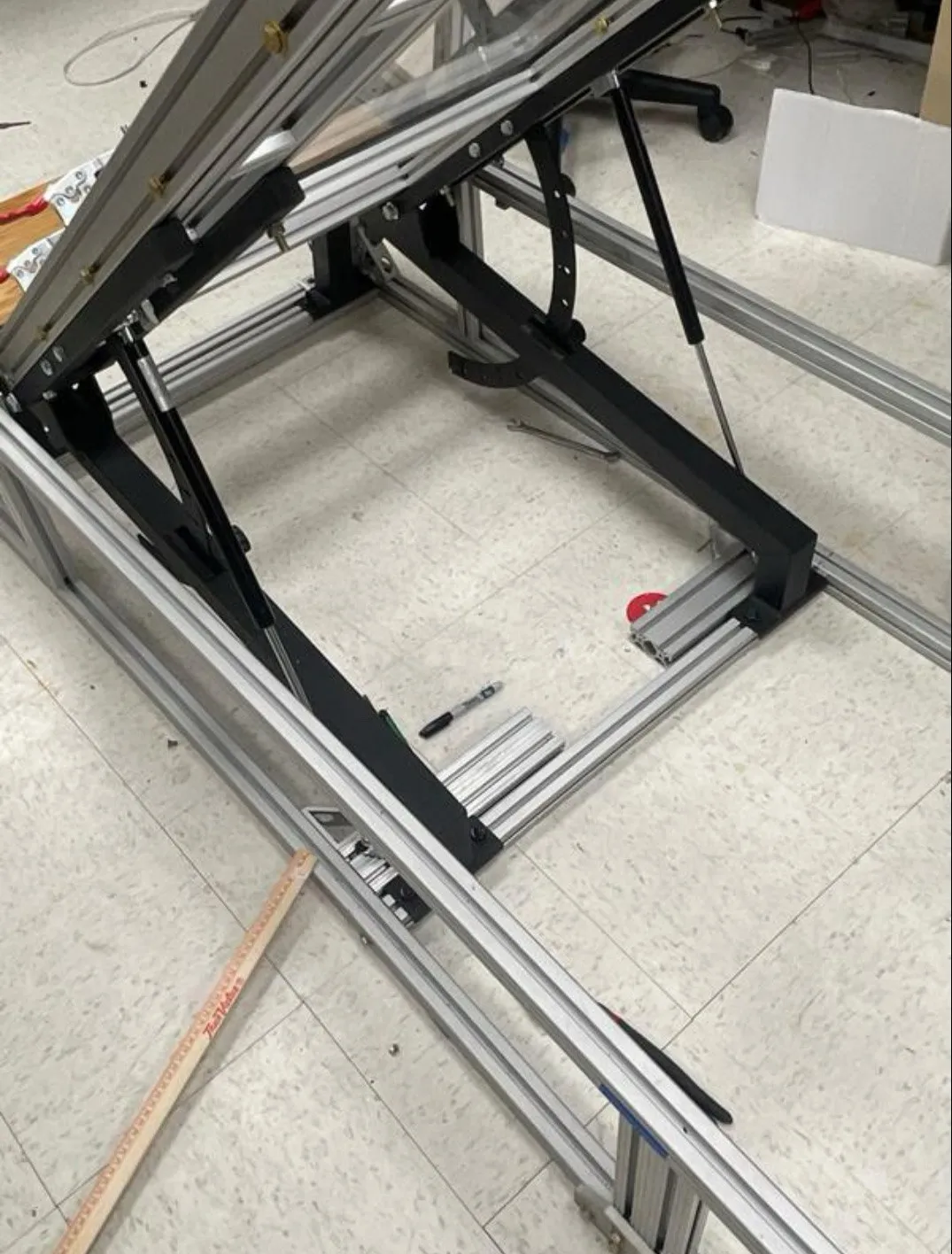
Why the plate is 0.75-inch cast acrylic
Four transparent surfaces made the material table: polycarbonate, acrylic, tempered glass, and structural laminated glass.| Property | Polycarbonate | Acrylic | Tempered / laminated glass |
|---|---|---|---|
| Yield strength | ~60 MPa | ~70 MPa | 120–200 MPa |
| Elastic modulus | 2.3 GPa | 3.2 GPa | 70 GPa |
| Impact resistance | 250× glass | 17× glass | baseline |
| Scratch resistance | Mohs 3 | Mohs 3.5 | Mohs 7 |
| Refractive index | ~1.58 | ~1.49 | ~1.52 |
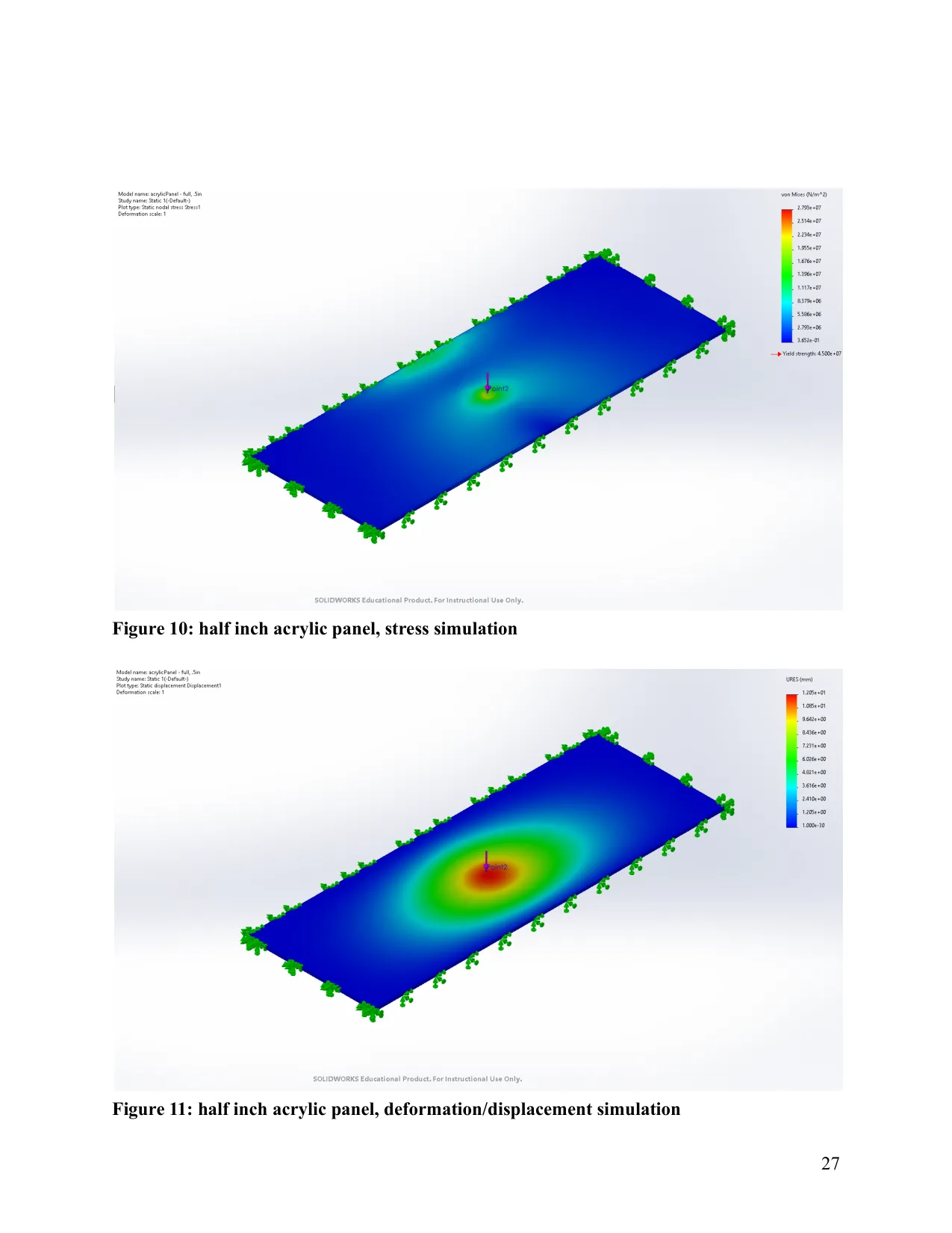
We shipped 0.75 in. Half-inch acrylic deflected an undesired amount; 1-inch was deemed too heavy for the average user to lift; 0.75 in withstands 300+ lb with minimal deflection and stays light enough to lift with the gas strut assist. The fall analysis figures and the fall BOM are in the fall final report.
Finding the first part to fail
This was being delivered to a customer for their use, and I did not feel comfortable accepting risks and just letting them slide — every identified risk got a hand calculation plus FEA verification. Four rounds of FEA ran in SolidWorks Simulation across six months — too many complex geometries to stress-test accurately by hand. The failure points, analyzed one by one: the acrylic breaking, the frame holding it, the steel supports connecting frame to base, and the base itself. The gas strut load came from regular cantilever equations, the bolted supports got simple hand calculations first and FEA after, and the acrylic-and-frame FEA covered stress and deflection plus fatigue.
Rails, clamps, and casters around the acrylic
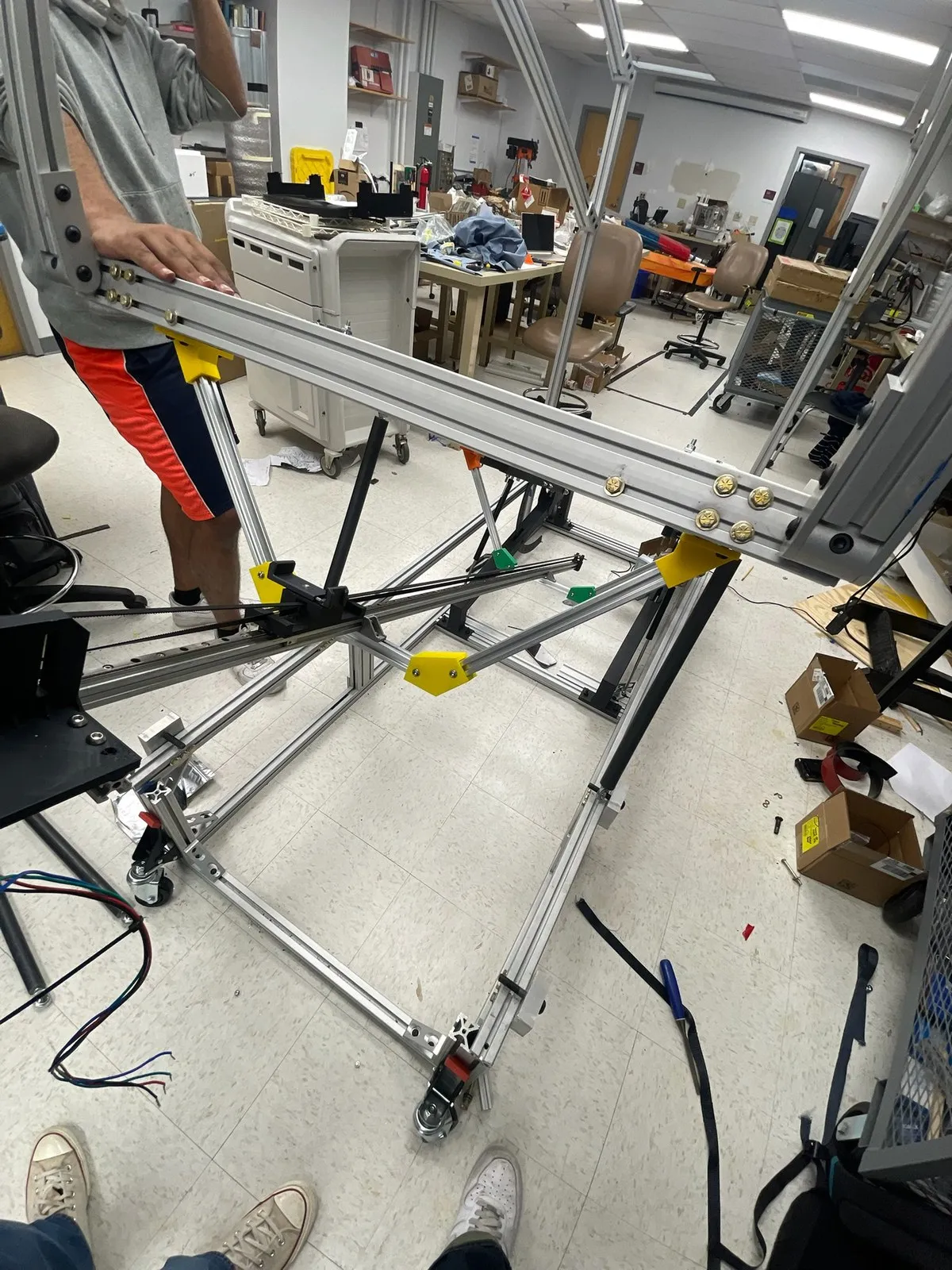
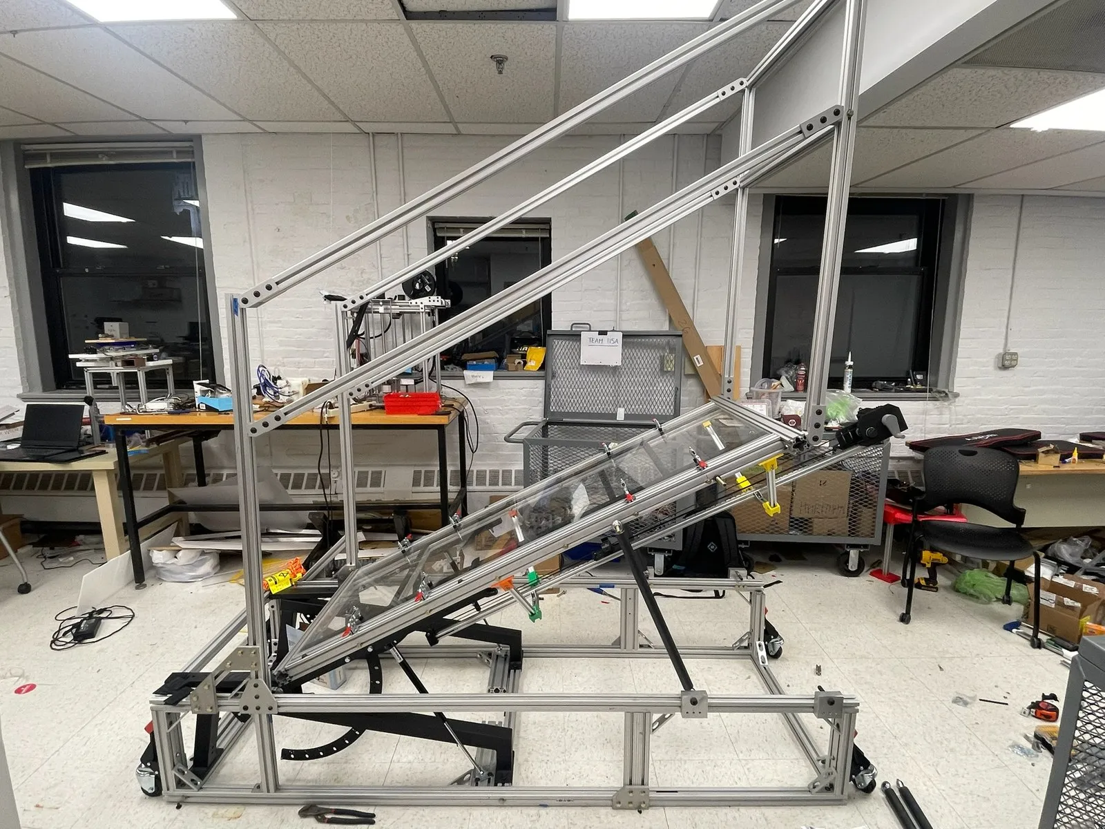
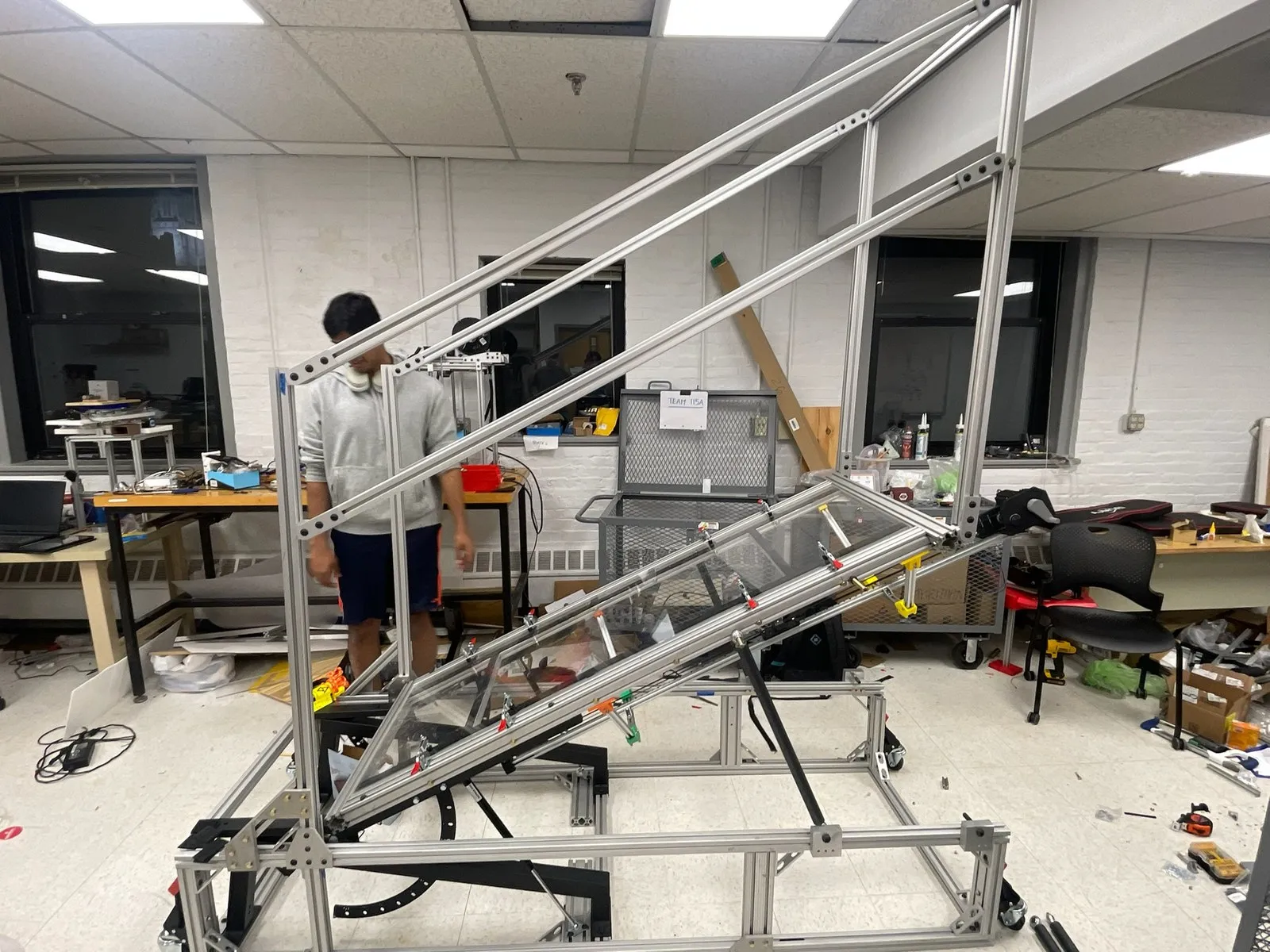
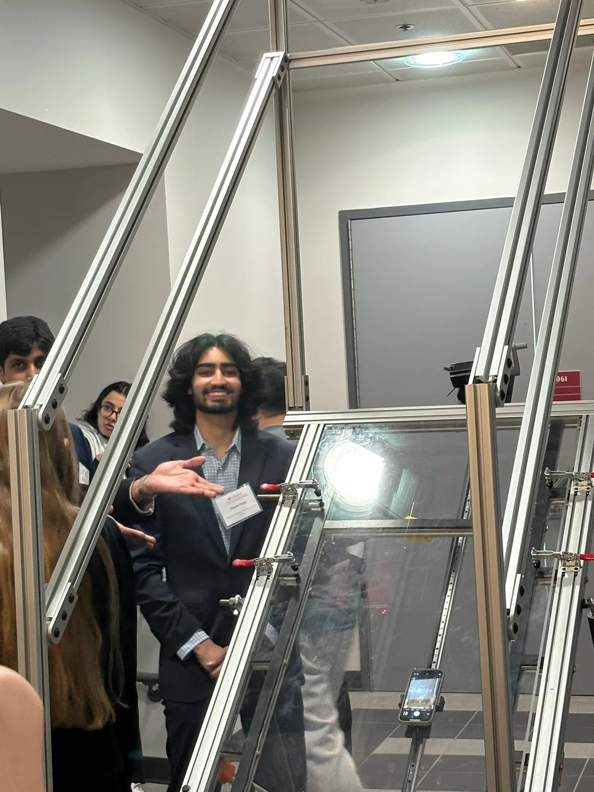
The stack, end to end: the 8020 base, the benches bolted into it, the acrylic ramp frame bolted to the bench tops, and the handrails, gas struts, end supports, and camera rail all hanging off the ramp frame. The acrylic rests on 1 × 1 in internal beams inside a 2 × 2 in 8020 perimeter, where rubber tape and toggle clamps keep it from moving while still letting a user pull the panel out in seconds — Vibram’s removability requirement.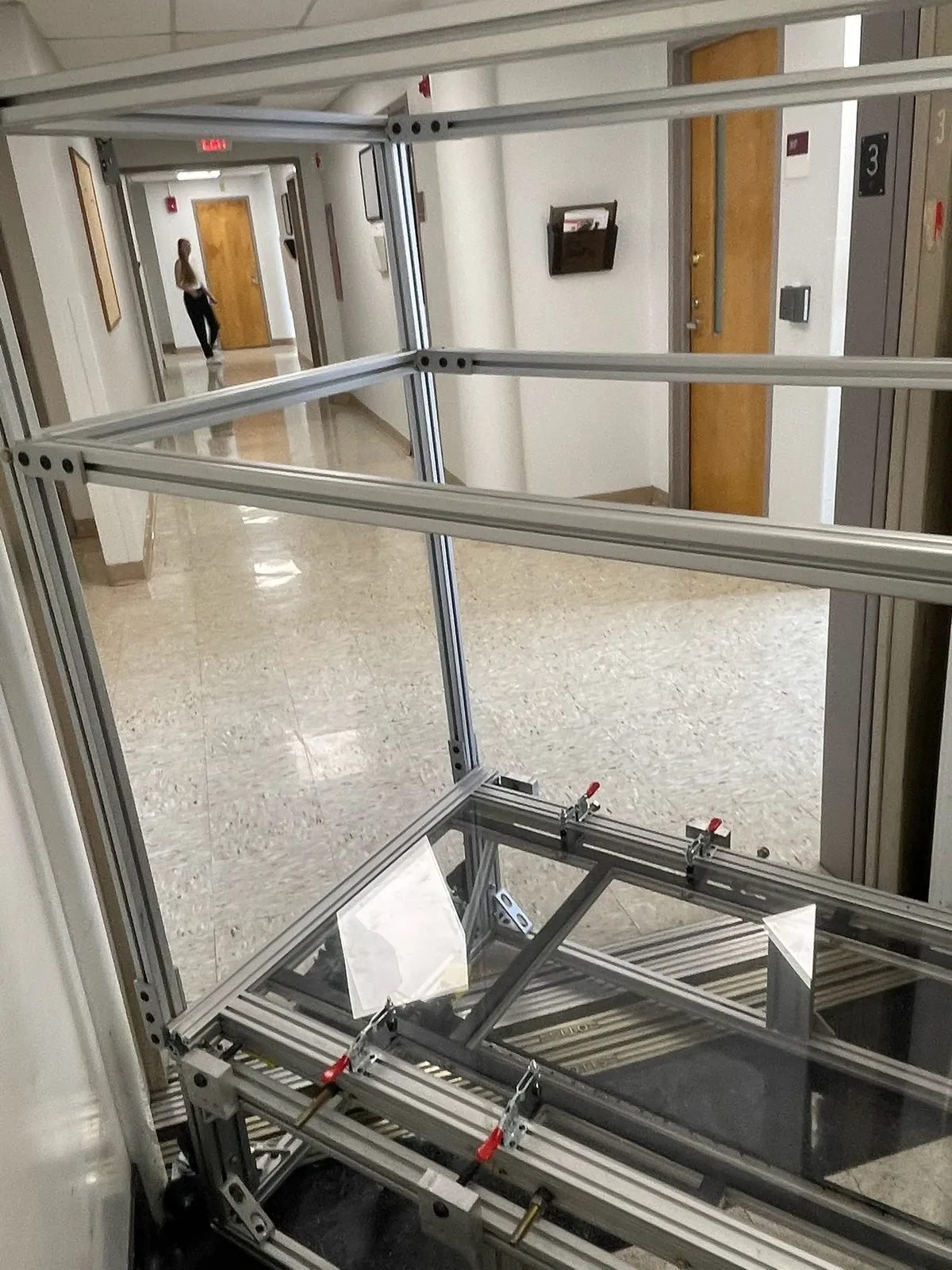
The camera system under the walkway
I led the camera research, and the requirement was strict: the camera below must stay perpendicular to the walkway at all times. In the spring the camera design questions went to me and a teammate, and I ran the subgroup that answered them — three of us, meeting notes mine. The recording decisions came first: a phone rather than a dedicated camera, because capture and export are easier, there’s no camera to buy, and it’s simpler for the user; continuous video through the phone’s native camera app instead of triggered stills, so Vibram can extract whatever they need from the footage; no data cable — the videos stay on the phone and export digitally; and the camera stays unmoved while filming so the picture is stable, mounted as far below the acrylic as the geometry allows. The phone mount we bought instead of printing: friction-fit prints aren’t universal and crack, tensioned universal prints rely on rubber bands, and a purchased universal mount cost about $16 — I ordered it. For driving the carriage we weighed a belt drive, very smooth but needing at least 10 feet of belt; a pulley-and-spool, very simple but easy to break; and a motorized drive, scrapped outright because this machine was to have no electromechanical components. What shipped is a phone holder on a linear rail under the acrylic, connected to a gear system: the user cranks the holder out from under the frame — the rail extends past the end of the ramp — loads their phone, cranks it back under, and controls it by remote while it’s underneath. The crank-out exists because I did not want the user to have to reach under and potentially put themselves in a pinch point or any danger.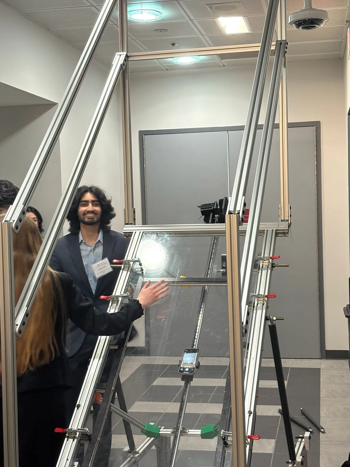
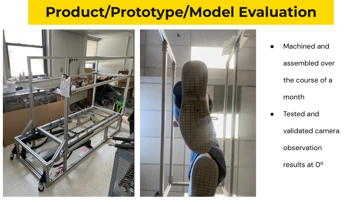
Machining and assembly
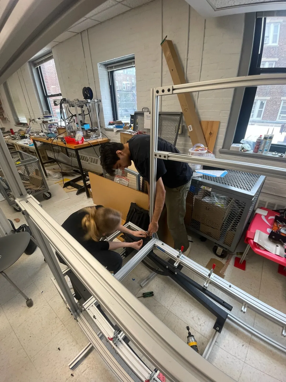
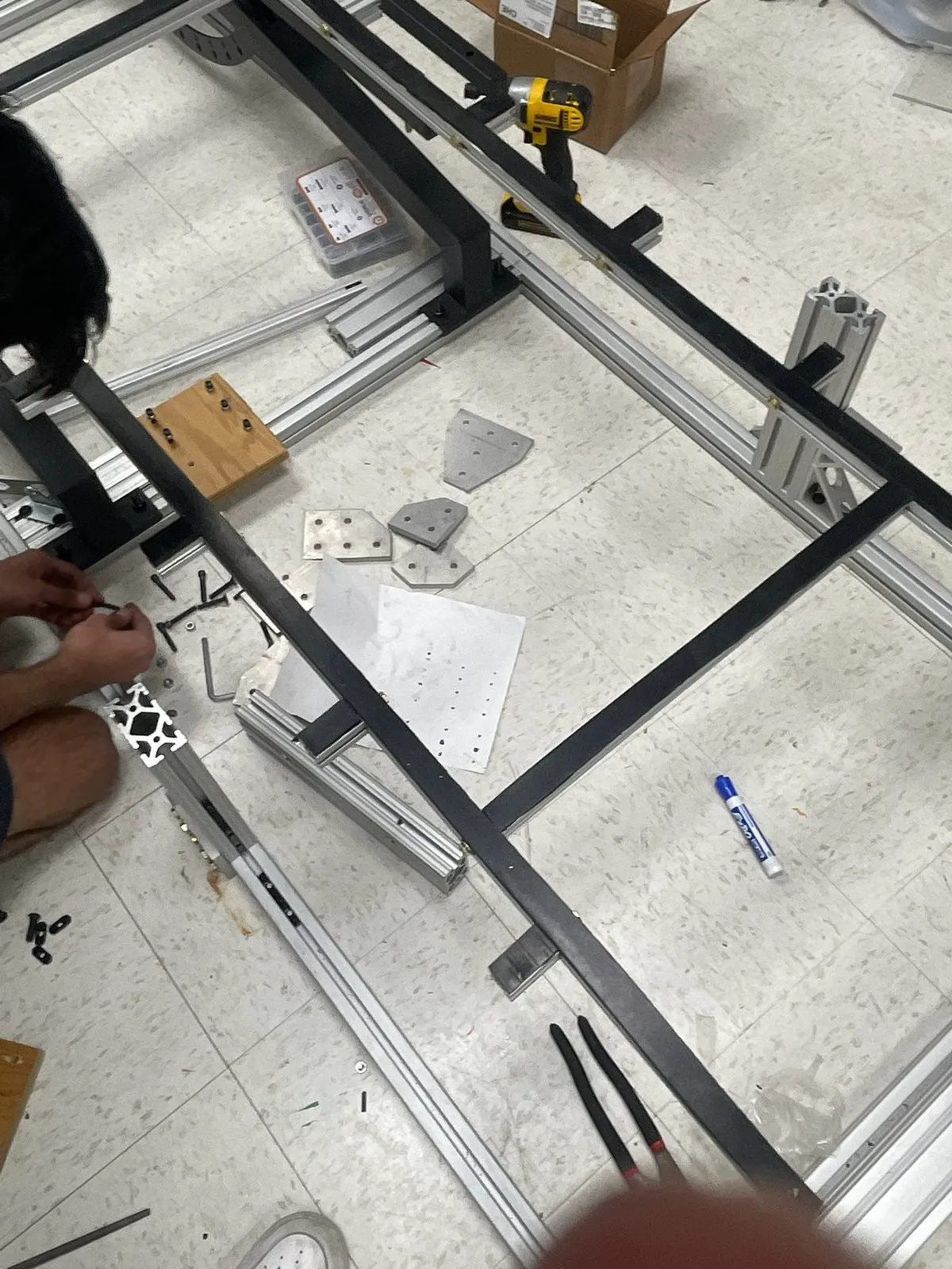
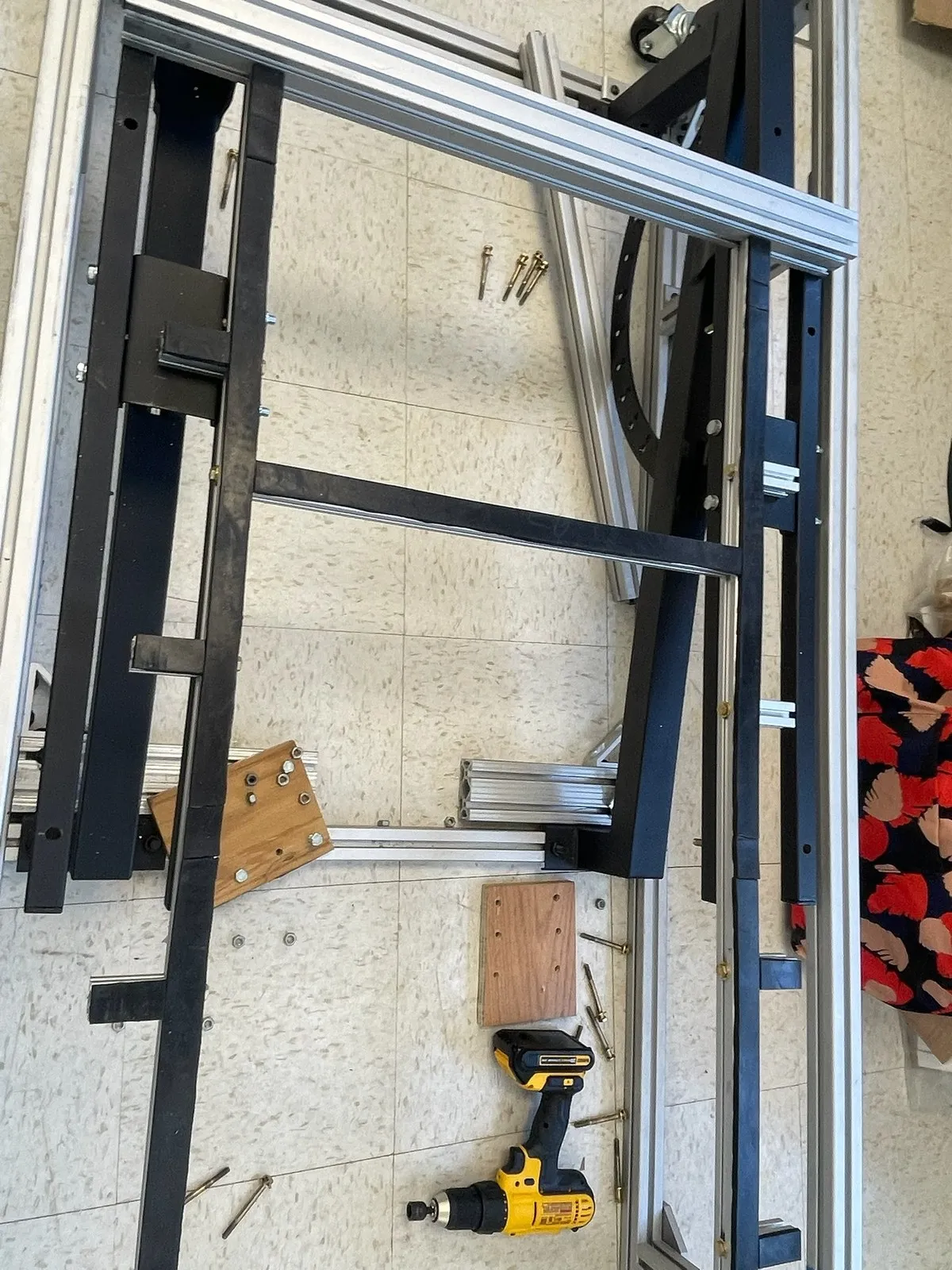
We had pretty much all of McMaster-Carr available as well as the machine shop at the school, and that led to a ramp consisting almost entirely of 8020. Manufacturing was mostly ordering 8020, cutting it to size on the cold saw, then drilling and tapping holes in the proper places — every part personally made by the team, with me leading the manufacturing. Each hole position was measured to within 1/16 in, with a tolerance stack-up at the places where components interface — every drilled feature had to land within tolerance for the all-bolted frame to go together easily and properly. Tapping was the workflow that broke first: the initial design required tapping the ends of many 8020 bars, which took too much time and effort, so I moved joints to the side of the extrusion instead of the end and used slide-in T-slot hardware instead of tapped holes. 3D printing shipped as real hardware here too — the pin-actuation connectors joining both bench pins to one beam are printed parts.
$2,500 target, $2,926.21 on the BOM
In September the budget was iffy to say the least: $500 from BU, no stated figure from Vibram, and their guidance was to pitch material purchases and design decisions with justifications whenever we asked for funding. So I assembled the budget in stages: $100 per person from the class — $500 for the five of us — an extra $700 I secured from the school that other projects weren’t using, and the remainder from Vibram after I presented the bill of materials and the design justifications.The final numbers disagree. The 2025-03-10 BOM, with buffer, totals $1,767.62 on Vibram’s side and $1,158.59 on BU’s — $2,926.21 combined; I remembered it as $2,500 of material. The BOM is the document, so $2,926.21 is the number I stand behind, above the $2,500 goal. The transparent plate the whole machine exists around was $278.00 of that. The line items, split by who paid, are in the bill of materials.
Load testing, lightest walker first
The validation plan was quite simply using it. Once it was assembled and all the supports were properly placed, I walked on it — I was the lightest member of the team, so I went first, and it held just fine. Then our heaviest member, at about 300 pounds, walked on it and did great. Two people stood on it at about 450 pounds total, and on that basis I felt comfortable checking off the safety-factor box. What we observed compared well with the hand-calc and FEA predictions, though nothing was recorded as a number on test day.What the walk-on never proved
The walkway was never physically loaded to the full 500 lb design load; I overdesigned the safety requirements, and the final result was not tested up to the point FEA said was possible. Force to lift had a 40 lbf House of Quality goal and mean time before failure a 1-year goal, weighted 13%; neither was ever measured, and the finished unit was never weighed against its 350 lbf goal.Delivered to the Boston Connection Lab
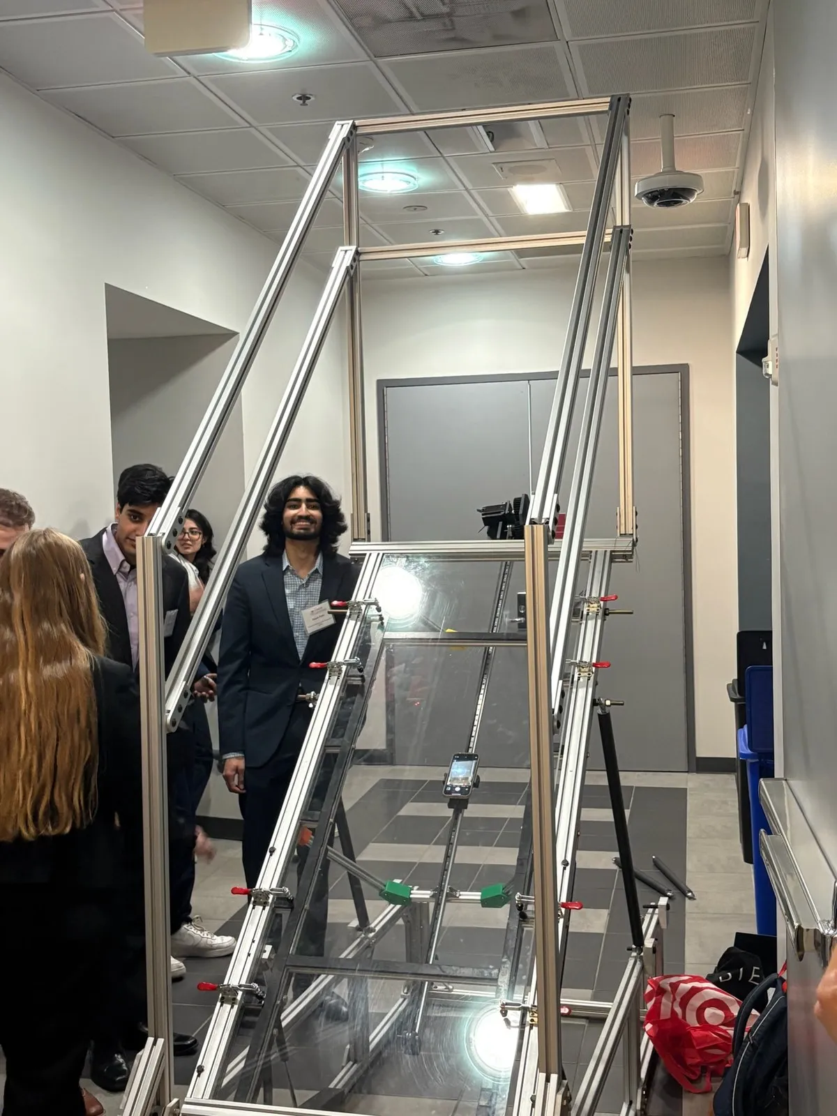
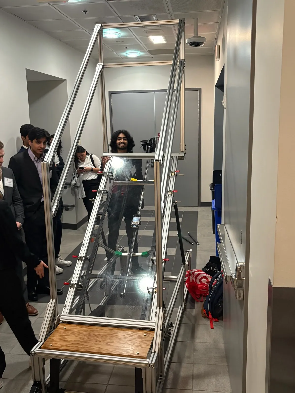
What went out the door in May 2025: the 2 × 5.5 ft, 0.75-inch cast acrylic walkway in its 8020 fixture with parallelogram handrails, gym-bench lift, steel supports, gas struts, casters, and the camera rail. Pretty much every single part was off the shelf — this was designed on a budget that could not use custom parts. That was deliberate: repairability was a selection criterion, and we handed over all documents and information at year end so Vibram could fix anything on their own.
The ramp 100% did its job — it supported weight and let video be filmed underneath without anyone reaching under it — and it is still in use at the Boston Connection Lab. Vibram’s contacts were engineers, we ran design reviews with them and our faculty advisor throughout, and they never said the work wasn’t what they wanted.What this project taught me
My biggest takeaway was bias to action: in meetings where people were uncertain, step up with a plan. The decision I’m proudest of is killing the beach chair: I’m not gonna go into the sunk cost fallacy here — even though we spent time designing this, objectively it will not work, we have to pivot. Technically, I learned a lot about assembly and tolerance, and about designing for manufacturability. Major decisions we made together; individuals were empowered to go off, make things happen, and come back prepared — infinitely better than sitting on your hands waiting for someone else to give you an answer. What I would do differently is be more decisive in design decisions — that was a big learning experience of this project. We could talk and talk about potential solutions, but in my experience the best way to get there is to try and fail, or try and succeed; failing fast is better than not trying at all. We were limited heavily by budget, so I do understand the hesitancy, but being more decisive would have saved a lot of time — time we could have used continuously improving the project.Gallery
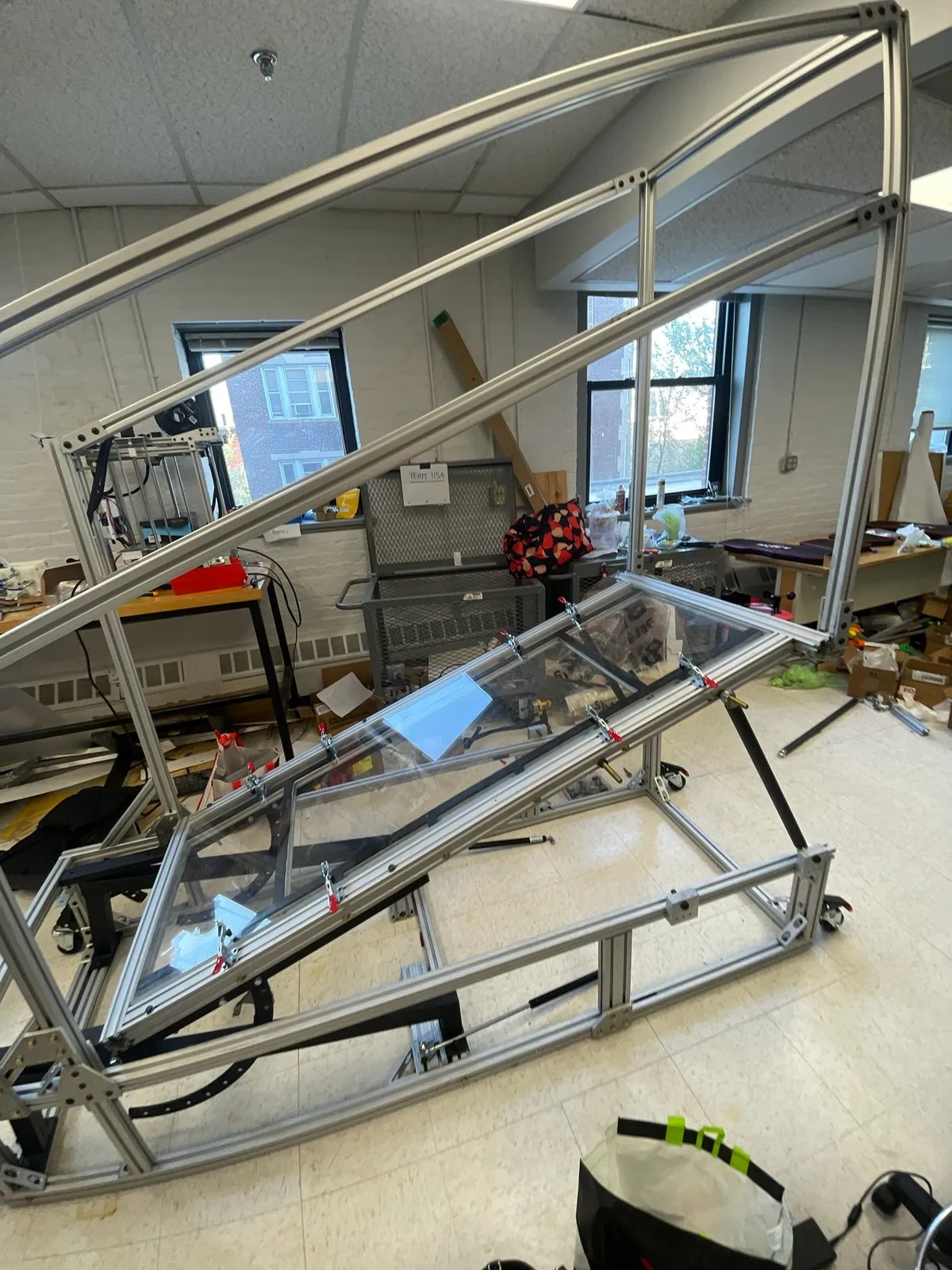
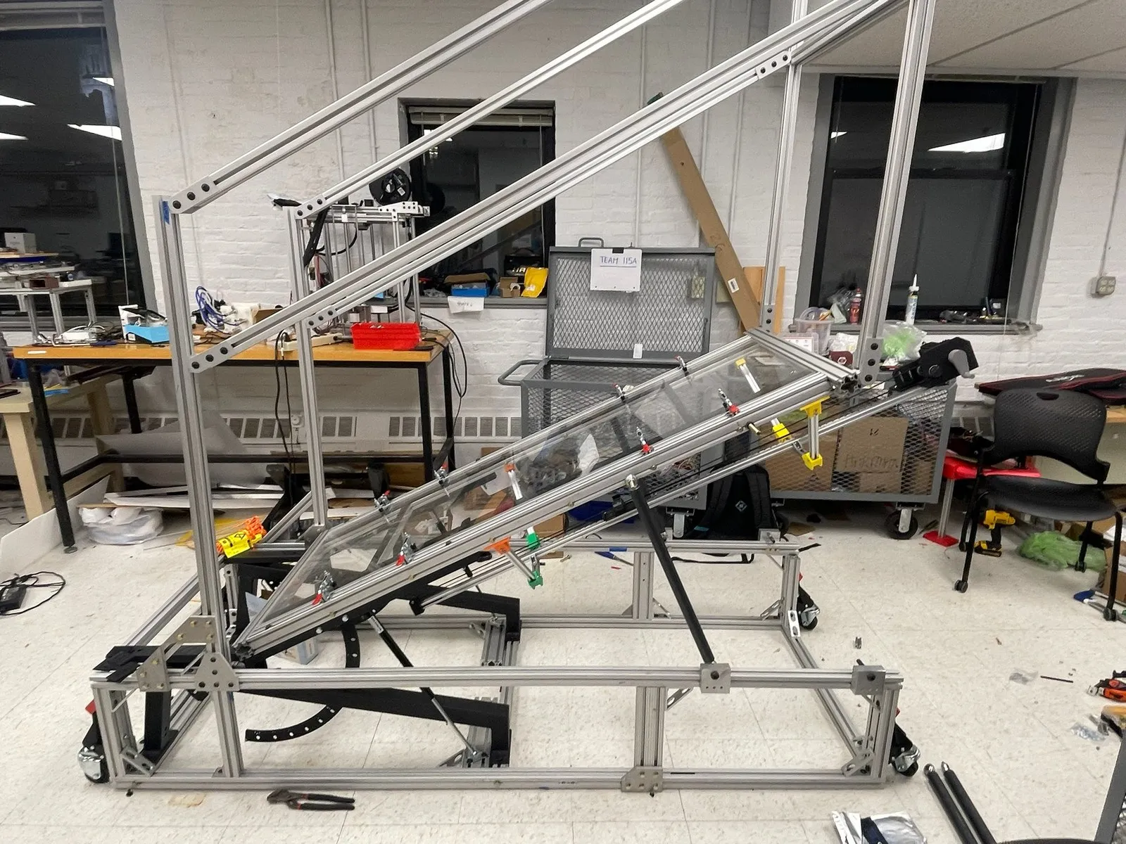
.BMnjiyru_dbnFE.webp "Validation was simply using it: we walked on it, lightest first, and measured behavior matched the hand calcs and FEA.")
.uktovgcy_HtFnY.webp "Rails were a hard safety requirement: the parallelogram handlebars stay parallel to the walkway with a vertical back bar at any angle.")